GO FISHING, use SLABSAUCE Fishing Attractant
Results 1 to 6 of 6

Thread: sword circuit diagram

  1. #1
    Join Date
    May 2004
    Location
    Japan
    Posts
    9,250

    Default sword circuit diagram


  2. #2
    Join Date
    Jan 2007
    Location
    Dayton Ohio
    Posts
    1,483

    Default

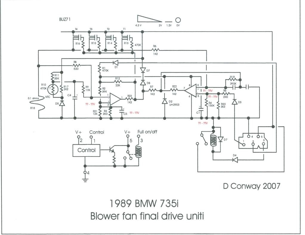
    The jpeg is to light to print out and then read. So I recreated it in Corel draw and have uploaded to Photobucket. There are a couple places were I could not read what was written and I labeled those in red. Can you contact D Conway to get the data, or anything else he would want to include on the drawing.

  3. #3
    Join Date
    May 2004
    Location
    Japan
    Posts
    9,250

    Default

    Maybe this helps, Tim Meek on the E32 U.K. board was trying
    http://www.meeknet.co.uk/e32/E32_Sword_Diagram.jpg
    his comments
    Well done Erich, that's the first diagram I've seen of the Sword that looks correct! Interesting to see that it actually has a current-limit (LHS of the diagram) which is temperature-compensated. Here is the same diagram, the right way up and adjusted so you can read it

    I will now post yours there and post back any comment, so that you can complete it

  4. #4
    Join Date
    May 2004
    Location
    Japan
    Posts
    9,250

    Default

    reply from Tim:
    Erich, there were a few errors on both diagrams....so I have produced one myself. It looks like it could work with the values as shown, however, if anyone thinks there is an error let me know:
    http://www.meeknet.co.uk/e32/BMW_E32...Unit_Sword.pdf

    answer C8 SDD:
    Bit strange how the "output" feeds from the centre of the layout?

    Most tv and radio circuit diagrams i've seen have the "heavy" current devices over on the
    right hand side.
    You could say they flow from left to right ... 98/100 for effort though.


    reply Timm:
    Yes, a bit of a strange circuit this one, the control comes from two directions, which excluded the usual left-to-right circuit flow. Still, at least it makes a bit more sense now......

  5. #5
    Join Date
    Jan 2007
    Location
    Dayton Ohio
    Posts
    1,483

    Default

    Very good... I can now pitch mine

  6. #6
    Join Date
    May 2004
    Location
    Japan
    Posts
    9,250

    Default

    got this info:

    From left to right,
    the voltages are 4.5V 2V 1.8V 0V
    R13 to R16 = 470R
    the voltage on pin 3 is 0.3V.
    the -ve opamp input should be pin 2, not 1
    C5 is 3.3uF, 35V
    the writing between pins 6 and 5 = 0.35V at full input
    C1 is 3.3uF, 35V


    BUZ71 is obsolete but substitutes are readily available.

    Regards

    Dazz

Similar Threads

  1. Anyone looking for a sword
    By nirvana19 in forum 5 Series BMW
    Replies: 0
    Last Post: 11-04-2007, 02:24 PM
  2. 540i -93 M60B40 oil circuit diagram
    By blitzi in forum 5 Series BMW
    Replies: 1
    Last Post: 04-11-2006, 02:24 AM
  3. BMW sword
    By xtmsports in forum 5 Series BMW
    Replies: 4
    Last Post: 10-29-2005, 12:13 PM
  4. Sword
    By Rory535i in forum 5 Series BMW
    Replies: 8
    Last Post: 04-12-2005, 09:59 AM
  5. I've got my sword out!
    By Bimmer Nut Ed in forum 5 Series BMW
    Replies: 11
    Last Post: 09-07-2004, 05:47 PM

Posting Permissions

  • You may not post new threads
  • You may not post replies
  • You may not post attachments
  • You may not edit your posts
  •